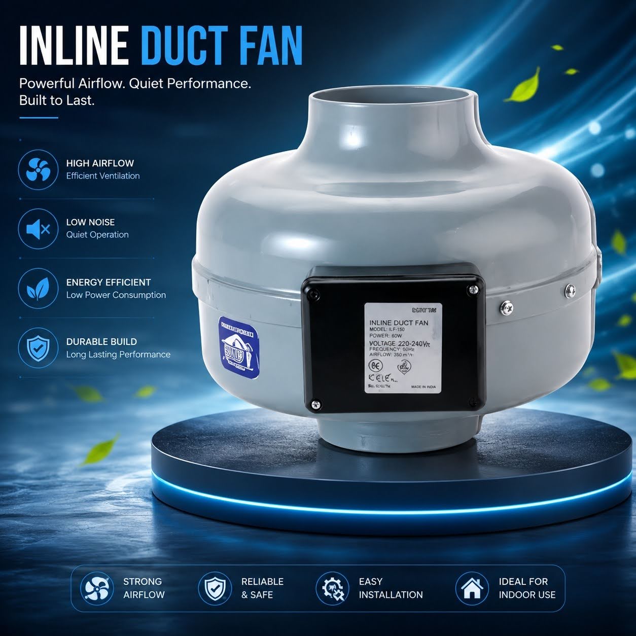
When a facilities manager or contractor selects a ventilation fan for a commercial application, the number that receives the most attention is almost always CFM — cubic feet per minute, the volumetric measure of how much air the fan moves. The CFM rating appears prominently in product specifications, and the intuitive approach to fan selection is to calculate the air volume of the space, determine how many air changes per hour are needed, and find a fan whose CFM rating matches or exceeds the calculation.
This approach produces a result that looks correct on paper and frequently underperforms in practice. The reason is a variable that rarely appears in the simplified version of the fan selection conversation: static pressure.
What static pressure actually is.
Static pressure in a ventilation system is the resistance that air must overcome as it moves through ductwork, fittings, filters, grilles, and any other components between the fan’s inlet and outlet. It is measured in inches of water column (in. w.g.) and represents the cumulative friction and turbulence losses that the moving air encounters throughout its path.
A fan operating in free air — with no ductwork, no restrictions, no fittings — experiences zero static pressure and delivers its maximum rated CFM. This is the condition under which most fan CFM ratings are measured and reported. In any real-world installation, however, the fan is connected to a duct system, and that duct system imposes static pressure that reduces the actual airflow the fan delivers.
The relationship between static pressure and airflow is captured in a fan’s performance curve — a graph showing CFM at different static pressure values. A typical fan might be rated at 1,500 CFM at zero static pressure, 1,200 CFM at 0.25 inches of water, 900 CFM at 0.5 inches, and 400 CFM at 1.0 inch. Select that fan for a system that turns out to impose 1.0 inch of static pressure, and the installed airflow will be roughly a quarter of the labeled maximum — not enough to perform the ventilation function the system was designed around.
Why duct systems generate more static pressure than most designers account for.
The static pressure that a duct system imposes is the sum of friction losses from multiple sources: straight duct runs (where friction between moving air and duct walls accumulates per linear foot), fittings and transitions (where changes in direction, diameter, or shape create turbulence that disproportionately increases resistance), filters and media (which impose significant resistance, particularly as they load with particulates), dampers and louvers, and terminal grilles or diffusers. Each element contributes to the total system static pressure, and the cumulative total in a real installation is frequently higher than simplified design calculations anticipate.
Elbows and transitions deserve particular attention because their contribution to static pressure is often underappreciated. A single 90-degree elbow in a round duct can impose an equivalent pressure loss equal to several feet of straight duct, depending on the radius of the elbow and the duct diameter. A poorly designed duct routing with multiple direction changes may impose three to four times the static pressure of a direct run of the same length. Filters that are specified for their particle capture performance but not evaluated for their pressure drop at design airflow can add 0.5 to 1.0 inch of static pressure or more to the system total.
What happens in installations where this is ignored.
The consequences of selecting a fan without accurately accounting for system static pressure are predictable and common. The most frequent outcome is simply inadequate airflow: the fan runs, makes noise, and gives the appearance of functioning, while delivering substantially less air movement than the ventilation design requires. In a simple office exhaust application, this may mean slightly elevated CO₂ levels and reduced fresh air delivery — uncomfortable but not immediately obvious.
In applications where ventilation serves critical functions — commercial kitchen exhaust, spray booth ventilation, grow room climate control, server room cooling, or fume extraction in manufacturing — the shortfall has more serious consequences. A commercial kitchen operating with exhaust fans that are delivering 60 percent of their designed airflow is accumulating heat, grease-laden air, and combustion products at a rate the ventilation system was not built to handle. A spray booth with insufficient exhaust velocity is not maintaining the air velocity required by NFPA standards for explosion protection. A grow room with undersized air exchange is developing humidity and CO₂ concentration profiles that will damage crops and promote mold growth.
In all of these cases, the fan was selected at the right nominal size. The static pressure calculation was missed.
How to match fan selection to real system conditions.
The correct approach to fan selection for any ducted application begins with a system static pressure estimate — calculating the expected resistance of the actual duct layout, including all fittings, components, and terminal devices — before identifying the fan. Once a system static pressure estimate is available, the fan can be selected by finding a unit whose performance curve shows adequate CFM at that estimated static pressure value, not at the zero static pressure maximum.
This is why Global Industrial duct fans are specified with performance curve data rather than single-point CFM ratings — the curve provides the information needed to match fan performance to the actual installed conditions. For straightforward applications with short, simple duct runs, the static pressure is low and the rated CFM approximates installed performance reasonably well. For longer runs, complex layouts, or high-resistance components, the performance curve is the only reliable guide to what the fan will actually deliver.
The sizing error that produces the most preventable failures.
There is a secondary static pressure error that is actually more common than undersizing: the oversized fan installed in a low-resistance system. When a fan is oversized relative to the duct system’s actual static pressure, it operates toward the left end of its performance curve — in the high-velocity, low-pressure region where airflow can become turbulent, noise increases significantly, and in some fan designs, the motor may overload because the reduced resistance allows the fan to draw more current than its rated load. The result is a noisy, potentially unreliable system that often consumes more energy than a correctly sized alternative would.
The ideal installation is a fan selected to operate at or near its design point on the performance curve — the region of maximum efficiency — under the system’s actual static pressure conditions. This requires knowing both the system resistance and the fan’s full performance curve. It is not a complicated calculation, but it is one that is consistently skipped in favor of the simpler CFM-matching approach that produces so many of the ventilation problems that facilities teams spend years trying to diagnose and repair.
Static pressure is not a footnote in the fan selection process. It is the variable that determines whether the process produces a system that actually works.